Time Delay Relay Circuit Using Transistor

10 Sec To 30 Min Time Delay Circuit With Relay Transistor Eleccircuit Com Basic Electronic Circuits Simple Electronic Circuits Circuit

How To Build Time Delay Relay Circuit Circuit Diagram Circuit Relay

One Transistor Relay Delay On Timer Circuit Circuit Projects Electronics Circuit Electronic Circuit Projects

10 Sec To 30 Min Time Delay Circuit With Relay Transistor Eleccircuit Com Basic Electronic Circuits Simple Electronic Circuits Circuit

10 Sec To 30 Min Time Delay Circuit With Relay Transistor Eleccircuit Com Basic Electronic Circuits Simple Electronic Circuits Circuit
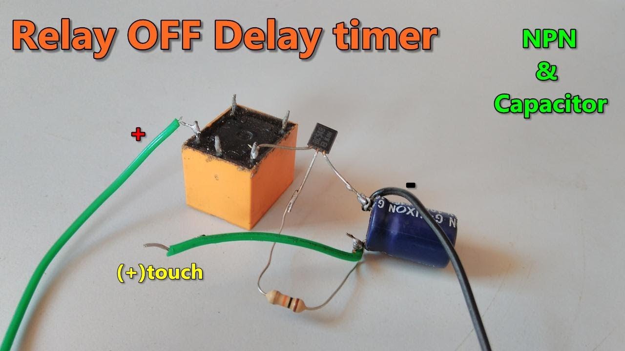
Relay Off Time Delay Timer By Using Npn Transistor And Capacitor Youtube In 2020 Relay Transistors Timer

Here i present a very easy and simple circuit of on time delay timer circuit which is made using 2 transistors some resistors and a capacitor.
Time delay relay circuit using transistor.

Thermostat Delay Relay Timer Circuit Homemade Circuit Projects Circuit Projects Circuit Thermostat

Adjustable Timer Circuit Diagram With Relay Output Electronic Circuit Projects Circuit Diagram Circuit

Mosfet Timer Circuit Simple And Easy To Make Electronic Circuit Projects Circuit Timer

Here We Discuss How We Can Make Simple Delay Timers Using Very Ordinary Components Like Transist Circuit Projects Electronic Circuit Design Electronics Circuit

Simple Time Delay Circuit Using Mosfet Eleccircuit Com Circuit Dc Circuit Electronics Projects

Pin On Wiring

1 Minute Timer Circuit Diagram Circuit Diagram Timer Circuit

Pin On Led

Simple Compact Transistorized Timer Circuit Circuit Projects Electronic Circuit Projects Electronics Circuit

Simple Time Delay Circuit Diagram Using 555 Timer Circuit Diagram Electronics Circuit Circuit

Timer Switch Circuit Diagram For Light

Basic Timer Using Fet 2n3819 Timer Electronics Circuit Electronics Projects

Simple Delay Timer Circuits Explained Homemade Circuit Projects Electronic Circuit Projects Electronics Circuit Circuit Projects

Timer Circuit Diagram Circuit Diagram Rc Timer With Op Amp 741 From Electronics Circuit Diagram Bbc Good Food Recipes Diagram

Simple Time Delay Circuit Using Mosfet Eleccircuit Com Circuit Electronics Technology Electronic Gifts

Pin On Willcotronix

Homemade Circuit Projects Simple Delay Timer Circuits Explained Circuit Projects Electronic Circuit Projects Electronics Circuit

Mini Circuit Projects Timer Circuits Emergency Light Hobby Circuits Here We Discuss How We Can Make Simple Electronics Circuit Simple Circuit Circuit Projects
Https Encrypted Tbn0 Gstatic Com Images Q Tbn And9gcsxqh4rcdxaqw Db Kroaef 8a Fjjkkobpnrui7a3vuosiz41s Usqp Cau

Make This Simple Delay On Timer Circuit Application Note Included Homemade Circuit Projec Electronic Circuit Projects Circuit Projects Electronics Circuit

Pin On Dan

Pin On Electrical Technology

In Many Electronic Circuit Applications A Delay Of A Few Seconds Or Minutes Becomes A Crucial R Electronic Circuit Projects Circuit Projects Simple Electronics

10 Sec To 30 Min Time Delay Circuit With Relay Transistor Eleccircuit Com Transistors Relay Delayed
Source : pinterest.com
